
Gimbal Bounding Box Tracking
Problem Statement
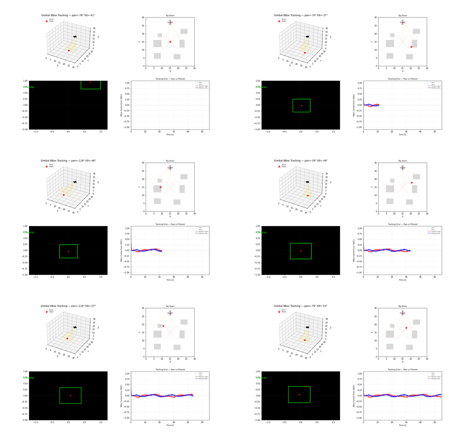
Bounding-box tracking aligns camera orientation to maintain target centering and approximate scale regulation in image space. It is a practical visual-tracking controller when depth is partially observable.
Model and Formulation
Let (u,v) be target center and (u^*,v^*) desired image center. Error:
PD control with smoothing:
Algorithm Procedure
- Detect target bounding box each frame.
- Compute center error and filtered derivatives.
- Convert error to pan-tilt command increments.
- Handle target loss with hold-and-search behavior.
Tuning and Failure Modes
Normalised device coordinates are not angles. NDC spans the entire field of view over
[-1, 1], so converting requires the FOV:θ = arctan(ndc · tan(fov/2)). Feeding NDC straight into a positional gimbal command makes the loop's real gain depend on the lens — with a 0.6 rad FOV, one unit of NDC is about 3.2 radians of apparent gain. The loop runs far past its stability limit and bounces between its rate limits, which reads as a tracking error but is a limit cycle.Command an angular rate and integrate it, so the gimbal's own rate limit is a limit rather than the only thing holding the loop together. Gains are then in 1/s and the closed-loop time constant is
1/k_p.A pan-tilt gimbal has a singularity on its own zenith. With the target passing directly underneath, bearing sweeps through π faster than any finite slew rate can follow. The resulting loss of lock is geometry, not control — put the observer beside the ground track, not above its centre. Doing so takes mean pointing error from 0.285 to 0.046 NDC.
Large derivative gain amplifies detector jitter.
Heavy filtering reduces noise but adds tracking lag.
Persistent target dropout requires robust reacquisition logic.
Implementation and Execution
python -m flybots.simulations.sensors.gimbal_bbox_trackingEvidence
References
- Chaumette and Hutchinson, Visual Servo Control Part II (2007)
- Szeliski, Computer Vision: Algorithms and Applications