
Visual Servoing
Problem Statement
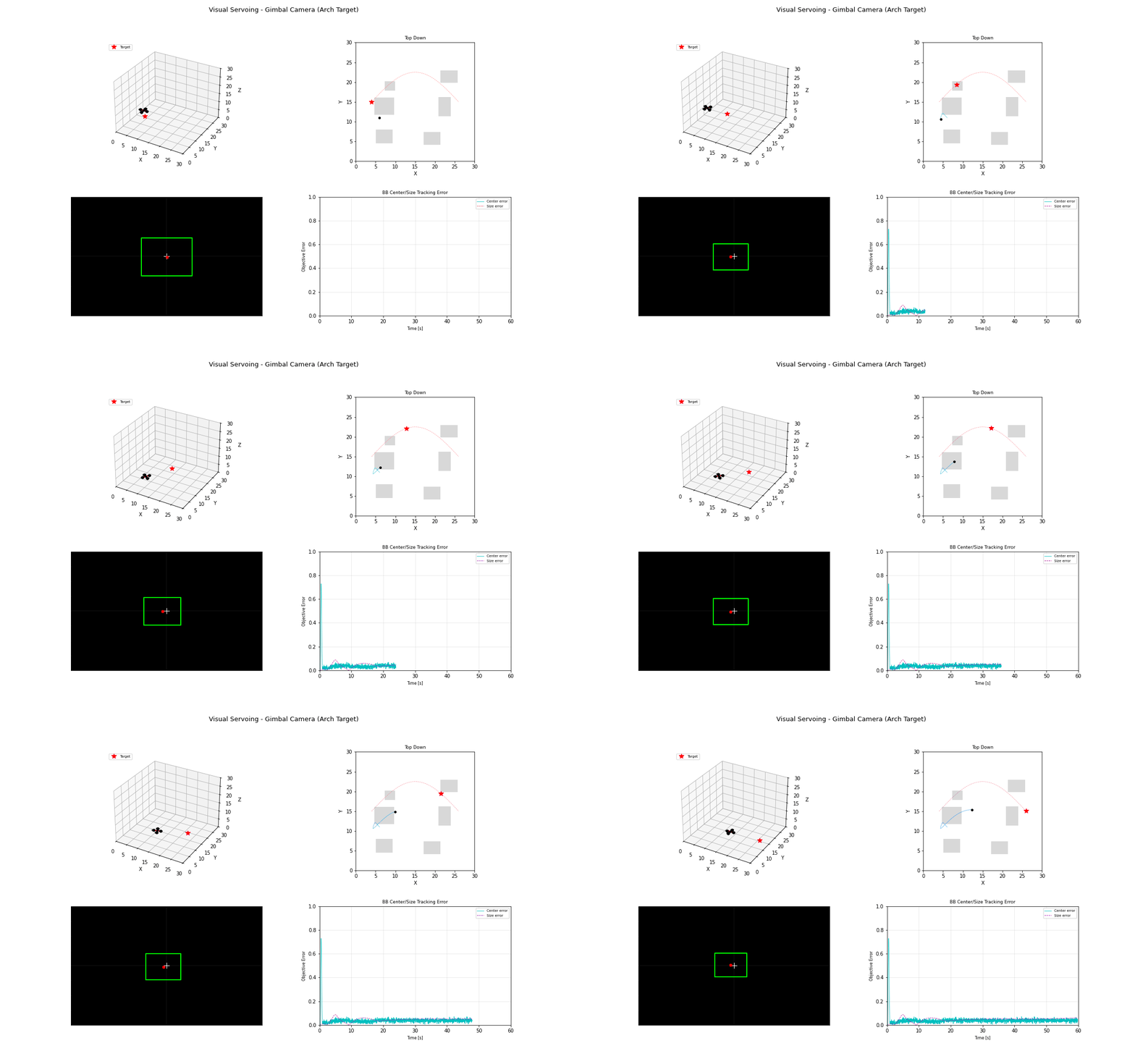
Visual servoing controls UAV motion directly from image-space error signals. It is effective for target following and precision alignment when full 3D reconstruction is unavailable.
Model and Formulation
Given image feature error e = s - s^*, the control law is:
where L_s is the interaction matrix and L_s^+ its pseudo-inverse. In bounding-box tracking, feature vectors include center and area terms.
Algorithm Procedure
- Extract target feature in image frame.
- Compute feature error to desired setpoint.
- Convert image-space error to body-frame commands.
- Apply velocity/attitude commands with saturation limits.
Tuning and Failure Modes
Check the sign convention before the gains. Image
+xis right and+yis down, while body+yis left and world+zis up (FLU/ENU), so both image errors flip sign entering the control law. Get one wrong and the drone chases the target out of frame — positive feedback that looks like an unstable gain.A gimbal changes what the drone should servo on. With an actively pointed camera the bounding box sits at the image centre whatever the drone does, so image-centre error carries no information about where to fly. The gimbal angles carry it instead: non-zero pan means the target has drifted off the nose, and a tilt steeper than nominal means the drone is too high. Range still closes on apparent size.
Do not close yaw through the gimbal's own pointing loop. Commanding
yaw = yaw + panputs two pointing loops in series chasing each other; the heading winds up and takes the position controller — which resolves tilt through yaw — with it. Slew the airframe toward the target bearing at a bounded rate instead, and let the gimbal own the fast loop.Anchor the position setpoint to the current position. Integrating a velocity command into a persistent setpoint means that once the position loop starts lagging, nothing in the image pulls the setpoint back.
Gain
\lambdatoo high causes oscillatory camera motion.Target occlusion can destabilize command generation without fallback logic.
Camera latency and rolling shutter distort high-speed tracking.
Implementation and Execution
python -m flybots.simulations.perception.visual_servoingEvidence
References
- Chaumette and Hutchinson, Visual Servo Control Part I (2006)
- Chaumette and Hutchinson, Visual Servo Control Part II (2007)